97 / 100

Basic plastic product manufacturing PROCESS EXPLAINED

In the world of plastic product manufacturing, many different processes make it confusing which process is the best process for your unique product. This page will explain some of the most used processes, the material used in each, and each’s strengths and limitations. These will allow you to select the process that meets your unique MOQ, Engineering/Design, manufacturing, and COST requirements. The plastic manufacturing processes we will discuss are:

Table of Contents

plastic product manufacturingMachined ABS Plastic Tray
Machined ABS Plastic Tray

Plastic Machining Plastic Product Manufacturing

When machining plastic in Plastic Product Manufacturing is relatively endless machining process possibilities to machine plastics as long as the plastic is rigid, most thermoplastic plastic with a few thermosetting plastics can be machined.

Process

Any standard machining process can be used. Machining is one of the most underutilized processes since 3D printing became readily available. It is common to think that a prototype utilizing 3D printing is the lowest cost. Printing might be true for smaller parts, one, two, or five parts. However, more significant, more complex parts with runs from 3-25 machining can be the more economical and quicker

Strengths

Machining can be economical for quantities of 1-25 in 1-3 weeks

Limitations

Parts will have machining marks and are better suited for machine shops specializing in machining plastics with powder coating to give the part a more cosmetically pleasing look. Some plastic injection molding factories specialize in this type of machining.

Materials of Machined Plastics

They are relatively endless as long as they are rigid, mainly in thermoplastic plastic with a few thermosetting plastics that can be machined.

Thermoplastic Plastic Injection molding

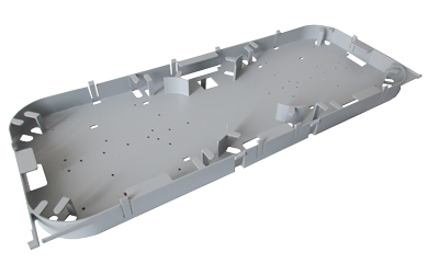
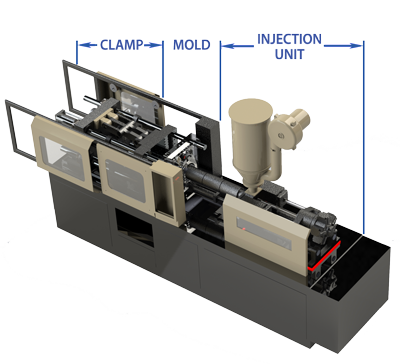
Plastic injection molding uses “thermoplastics,” plastics that melt with heat and inject the melted plastic into a mold cavity to create a cavity image, the finished plastic part. A typical plastic injection unit can be broken out and explained in three specific areas

A. The Thermoplastic Injection Unit

B. The Mold

C. The Clamp

The Thermoplastic Injection Unit:

The Plastic Injection molding Unit is comprised of 5 major parts:

  1. Injected Molded Plastic Pellet Hopper
  2. Injector Barrel
  3. Hydraulic Ram
  4. Heating Bands
  5. Reciprocating Screw

The injected molded plastic pellets are first put into the hopper in the plastic injection molding process, which feeds the Injected molded plastic pellets into the plastic injection unit’s barrel. As the reciprocating screw turns, the pellets are pushed forward and mixed by the injected molded plastic screw’s flutes/flights on the screw. The plastic injection molding screw diameter increases closer to the mold. The combination of the friction of the screw action and heat distributed by the heating bands, the injected molded plastic melts, and it is fed into the chamber in front of the screw. 

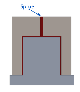
Then the hydraulic ram pushed the screw forward, injecting the mold sprue with the melted injected molded plastic in a matter of seconds. Most times, in less than seconds, the injected molded plastic component is ejected out of the mold, and the plastic injection molding process repeats itself. For larger plastic components and plastic housings, the timing will be longer.

Mold:

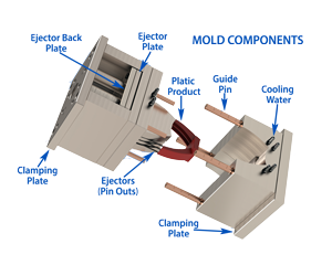
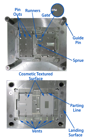
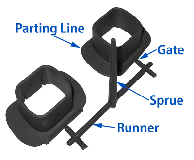
The Plastic Injection Mold is comprised of

    1. Clamping Plates: Two on each side to hold the mold, the “Mold Cavity Half” and the “Mold Core Half,” to the injection unit.
    2. Cooling Water inlets and Water Channels in the mold: this speeds up the process of thermoplastic solidification
    3. Guide Pins: Help guide the mold during operation.
    4. Ejector Back Plate:
    5. Ejector Plate: The Ejector Back Plate and Ejector plate hold the “ejector pins.”
    6. Ejector pins (or Pin Outs): Pins are used to eject the plastic part of the mold.

The Thermoplastic Mold Process in Plastic Product Manufacturing: The plastic injection molding process starts when the Injection Unit injects the melted thermoplastic into the sprue. This inlet feeds the thermoplastic into the mold cavity in a closed plastic mold. Cooling water is circulated in the mold through water channels to help speed up the Thermoplastic solidification. Once solidified, the mold will only slightly open a 1/64″-1/32 to break the vacuum for a couple of seconds the open all the way. 

The ejector plate and backplate move forward, pushing the ejector pins, which forced the finished plastic injection molding part and ejected it from the mold cavity. The ejector assembly moves back, the mold is closed, and the operation repeats itself in plastic injection molding.

Mold Design

Mold Design: When designing a part and having a plastic injection molding designed and manufactured to produce your part out of injected molded plastic, you need to have a more detailed understanding of design and mold components considerations to:

  1. Make sure your part can be manufactured or economically manufactured for injected molded plastic.
  2. Meet the part designers’ cosmetic expectations; the mold designer does not overlook them.

These considerations are (see the Mold Diagram) for injected molded plastic:

  1. Draft angles: A draft angle allows the Plastic part to be pulled from the mold with a reasonable force without damaging the final plastic injection molding product. If you made an injected molded plastic part with no draft angles, it would take a tremendous amount of force to remove the product from the mold and also could damage the part. Typical draft angles are from 1°-3°. The application and placement of these angles should be carefully discussed with the mold designer.
  2. Ejector Pins (Pin Outs): As discus previously in the Thermoplastic Injection Molding Process, ejector pins push the plastic injection process part of the core half of the mold. These pins are located in this core half and can be adjusted; however, there will be round “witness marks” where these ejector pins are located. The location should be discussed thoroughly with the mold designer so that it is not located on an injected molded plastic cosmetic surface.
  3. Shrinkage Cavities: These are caused by basically having too thick of a section in the design. This could because just from being thick or from a conjunction of a thick and thin part. The thickness is easy to correct by properly re-designing multiple sections or gussets to reduce the initial thickness.
  4. Parting Line: This is where the two mold haves come together. The two molds are never “perfectly aligned and could have a very slight radius. The parting line is often at the bottom of the injected molded plastic part, so it will not be cosmetically noticeable. If required on the side, not the parting line will be visible.
  5. Vents: These are machines into the landing face and are 10-50 µm to allow trapped air to vent out at the parting line; however, since the thermoplastic in the plastic injection molding process is viscous, the plastic will not flow through.
  6. Cosmetic Surface: Keep in mind the Injected molded plastic part is a perfect replica of the mold. So any surface imperfections or blemishes on the mold will be produced on the plastic parts’ surface. To remedy these imperfection, cosmetic surfaces are textured. The Plastic injection molding process has many different types and roughness textures that can be used. Remember that plastic textures cost money to produce and vary widely in cost. Discuss this carefully with the mold designer when considering plastic injection molding.
  7. Mold Cost: Mold cost can range from $2500 to $500,000+. Remember that mold designers typically design Plastic Injection Molding to do 500K-1M shots. Know your life cycle. If your life cycle is much lower than this, discuss this with your mold designer. This could save you 10-30% of the mold cost. Also, note molds are made from tool steel. For some parts, aluminum can significantly lower the mold cost but be aware of aluminum mold like only typically 10,000 to 50,000 shots. This is a good option if your design might change.
  8. Multi-cavity Molds: There are two considerations for multi-cavity molds. The first is to increase production; a single injected molded plastic part is made in the same mold as 2, 4, 6, and so on. This reduces cost and decreases production time. Second, you have an assembly, say with 2-4 injected molded plastic parts similar in size, but a lower production is needed. These multiple parts can be fitted in the same mold reducing the mold/NRE cost. There are other considerations when using a multi-cavity mold:
  • Runners: These channels allow thermoplastic flow to each injected molded plastic part cavity. Note that in a multi-cavity mold with runners, the sprue is contacted to the runners, not the injected molded plastic part.
  • Gates: these are reduction of the runner to the part cavity that regulates the flow to the cavity plus reduces the amount of area of plastic that needs to be cut from the part. This will leave a small noticeable mark at the parting line and not be in an area with high cosmetic requirements.

Clamp:

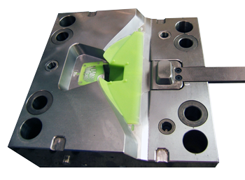
The clamp houses the mold in the thermoplastic injection unit for plastic injection molding. Before the injection process, the two halves of the mold must be mounted to the “clamp.” On either side of the clamp, there is a large stationary plate called the platen. Each side of the mold must be mounted to the corresponding platen. The front half of the mold, the mold cavity, is mounted to the front plate aligning with the plastic injection molding unit nozzle. The rear plate, the core half of the mold, is mounted to the rear platen that operates, moves the mold utilizing a large hydraulic ram for the injected molded plastic.

Strengths of the plastic injection Molding process:

  1. Very economical for single injected molded plastic part runs of 1000-100,000+; however, smaller runs of 250-500 with be produced with smaller parts.
  2. Very simple to very complex injected molded plastic shapes can be produced.
  3. Overholds was a sheet metal part that is molded into an injected molded plastic part that can be produced.
  4. A multitude of colors, transparencies, and materials are available in injected molded plastic.
  5. Can use regrinds, re-grinded scrap plastic from the Injection molded plastic process, and recycled material from the outside.
  6. I injected molded plastic has low labor costs.
  7. Short production lead time.

Limitations of the plastic injection Molding process

  1. High Injected Molded Plastic  Mold costs $2500 to $500,000+ depending on the plastic injected molding part’s size and complexity.
  2.  Injected molded plastic mold designs are complicated, if not impossible, to change. If there is a change possible, there will be a noticeable blemish in the mold; thus, a noticeable blemish in the plastic injection molded part.
  3. Lead time on the mold is 4-10 weeks, depending on the complexity of the injected molded plastic part.ion

Materials of Thermoplastic Injection Unit Process

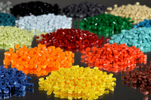
Thermoplastics in plastic injection molding come in injected molded plastic pellets that can be mixed to get the desired color or transparency:

  • POM/Acetal
  • PMMA/Acrylic
  • ABS/Acrylonitrile Butadiene Styrene
  • CA/Cellulose Acetate
  • PA/Polyamide (Nylon)
  • PBT, PET/Polyester – Thermoplastic
  • PES/Polyether Sulphone
  • PEEKEEK/Polyetheretherketone
  • PEI/Polyetherimide
  • LDPE/Polyethylene – Low Density
  • HDPE/Polyethylene – High Density
  • PPO/Polyphenylene Oxide
  • PPS/Polyphenylene Sulphide
  • PETG/Polyethylene Terephthalate Glycol
  • PP/Polypropylene
  • GPPS/Polystyrene – General purpose
  • HIPS/Polystyrene – High impact
  • PVC/Polyvinyl Chloride – Plasticised
  • UPVC/Polyvinyl Chloride – Rigid
  • SAN/Styrene Acrylonitrile
  • TPE/R/Thermoplastic Elastomer/Rubber
plastic-product-manufacturing Plastic injection molding machine
Plastic Injection Molding Machine
plastic injection molding Plastic Pellets
Plastic Injection Molding Plastic Pellets
Plastic Injection Mold Diagram Exploded
Plastic Injection Mold Diagram
Thermoplastic Injection Mold Design Key Features
Plastic Injection Mold Example Without Daft Angles
Plastic Injection Mold Example With Draft Angles
Part showing the Sprue, Runners, Gates and Parting Line
Multi-Cavity Plastic Part
Silicone Injection Molding LSR Liquid Silicon Spout
LSR Liquid Silicon Spout
Liquid Silicone Rubber Mold

LSR (Liquid Silicon Rubber) Injection Molding:

  1. LSR (Liquid Silicon Rubber) Injection Molding: this is a very similar process to the Thermoplastic Injection molding process with a few differences:
    1. Two-part material
    2. Two material holders
    3. Pump
    4. Mixer
    5. Hot Mold

Although the processes vary slightly between the LSR injection machines’ manufacturers, typically, the LSR (Liquid Silicon Rubber) Injection Molding starts with two buckets are barrels of different silicone components in plastic product manufacturing. These components are then pumped into a mixer. The mixed material is COLD. The LSR is then sent to a screw. Sometimes the screw will directly inject the LSR into the mold or send the mixed LSR to a separate plunger that injects the mixed LSR into a HOT (275F-390F) mold that rapidly solidifies the LSR part, and then the part is removed.

LSR Injection Molding Strengths Plastic Product Manufacturing:

  1. Very economical for 1000-100,000 part runs.
  2. LSR Injection Molding can be very simple to complex shapes can be produced.
  3. Short production lead time.
  4. FDA and Medical grade materials are readily available.
  5.  LSR parts can be used in high operating temperatures.

LSR Injection Molding Limitations:

  1. High Mold cost, $2500 to $500,000+ depending on the size and complexity of the LSR part.
  2. Mold designs are complicated, if not impossible, to change. If a change is possible, there will be a noticeable blemish in the mold, thus a noticeable blemish in the plastic injection prices part.
  3. Lead time on the mold is 4-10 weeks, depending on the part’s complexity.

Rubber/Silicone Compression Molding

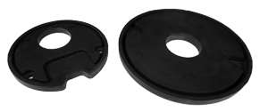
Rubber/Silicone Compression Molding: This is one of the oldest simple molding processes in plastic product manufacturing. Rubber/Silicone Compression Molding only has two major components:

A. The Mold

B. Compression Press

The compression molding process is also relatively simple. A premeasured amount of un-vulcanized rubber or silicone material, slug, is placed in one half or both halves of the mold. The mold is closed and heated to a predetermined time, and the rubber or silicone is vulcanized.

Strengths of the Rubber/Silicone Compression Molding

  1. In compression molding, the mold is at a lower cost than injection molding, especially on larger parts.
  2. Overhead & machine costs are lower.
  3. Per part, the cost of larger products is lower.
  4. Turnaround on mold is much faster than injection molds, 1-4 weeks.
  5. A good option for prototyping.

Limitations of the Rubber/Silicone Compression Molding

  1. The compression molding process is slower than injection molding, but this can be overcome by using multi-cavity molds.
  2. Part may have flashing that needs to be removed.
  3. Compression molding is not a good option for complicated parts.

Materials for Rubber/Silicone Compression Molding:

  • Neoprene
  • Viton
  • Buna
  • EDMP
  • Natural Rubber
  • Silicone
Compression Molded Silicone Gaskets

Conclusion, Processes

First, when you first select the correct plastic product manufacturing process, it comes down: what material you require, the NRE cost you can recuperate, and the physical geometry of the part to be manufactured.

Second, the last two items you must consider for plastic product manufacturing are a “Cradle to Grave” and a FULL-SERVICE COMPONENT CONTRACT MANUFACTURER. 

FULL-SERVICE means the contract manufacturer can provide you with a finished cast part including machining, PEM/Fastener installation, silk screening/engraving, and metal components if required, a “one-stop-shop“eliminating having to resend out your part for a secondary process to separate multiple vendors. This makes controlling processes errors from various sources difficult.

“Cradle to Grave” means as your plastic product manufacturing matures, we will continually give you suggestions (process changes, material changes, sub-assemblies) to reduce your cost giving you an improved sales advantage. An example would be at the beginning of marketing your product, PROTOTYPING. Your volumes are low, and you do not want to invest in molds and manufacturing quantity; Ionthis could make your finished part parts by machining from a solid block or unitizing an aluminum mold. 

Your NRE investment would be low, but the part price might be higher but absorbable. When your volume gets high enough to justify the NRE, Ionthis can move you into high-production molds. This is “Cradle to Grave.”

For a DFM/Analysis and recommendations of your Die-Cast, Investment Cast, and Sand Cast component or assembly, feel free to contact Ionthis at engr@ionthis.com. 

Request for Quote