When considering parts to be manufactured using a casting process, you must understand each process’s strengths and limitations to select the process that fits your unique requirements Engineering/Design, Manufacturing, and COST. This casting process selection is essential in the casting industry because casting factories typically only offer one type of process. Selection of the process that does not fit your unique needs could cost you an excessive amount of $s. The three processes discussed on this webpage are Sand Casting, Die Casting, and Investment Casting. We will discuss how the casting process works and then give you the strengths and limitations to provide you with a perspective on where to start.
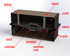
In sand casting, you form a cavity from a “pattern” when you pack the pattern between 2 box halves called flask split horizontally in the middle, the “parting line” with the top being the “cope” with the bottom being the “drag.” Patterns are the replica of the part you want to be manufactured, typically made from wood, plastic, and metal. Wood is the lowest cost because wood patterns can be quickly and easily made. However, wood can deform and wear out more quickly. Metal patterns are more expensive but are more accurate and last longer.
There are numerous kinds of sand that we will not cover here because they are more product application-focused but make sure to ask your supplier about the bents and drawbacks; they supply
You might need a “core,” which forms an internal cavity for more complex patterns. These casting cores are typically made from a resin base air or heat dried sand utilizing a steel mold to create. The cores are installed in the pattern then, after casting, cleaned out of the cavities.
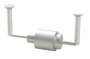
Also included in the mold are a “Sprue,” “Gates,” “Runners,” and “Risers.” The sprue is where the molten metal is poured into the mold. First, the runner is the channel that allows flowing molten metal to the gate, where the molten metal enters the pattern cavity. Second, the riser is where the excess molten metal goes after it leaves the cavity. The riser is essential to remove the impurities, have uniform heated material in the pattern cavity, and supply possible additional metal to the mold cavity during shrinkage.
First, the flask will be put on a flat surface like a heavy flat board in the sand casting process. Then ½ of the pattern is placed flat on a board, and the flask is filled with sand and packed and skimmed flat. This process forms the drag, and then it is flipped over.
Second, the top flask is put on top of the bottom, aligned with pins. The other half of the pattern is placed on top of the first half in the drag, usually aligned with pins or bolts. This is the ” Cope,” and these halves are now filled with sand and packed, forming the cope for the sand casting.
Third, the two halves are separated, so the pattern can be pulled out to form the casting pattern.
Forth, at this time, the “Sprue,” “Gates,” “Runners,” and “Risers” put in, and cores are placed in to form the cavities. Then the halves are put back together, ready for the molten metal to be poured into the sprue.
Fifth, the molten metal is then poured into the sprue from a ladle until it first comes out of the riser and is allowed to cool, forming the sand casting.
Last, the assembly is then “Shakeout,” removing the sand, and the cast part is removed with the “Sprue,” “Gates,” “Runners,” and “Risers” to be later removed from the sand casting.
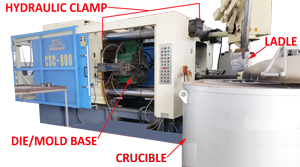
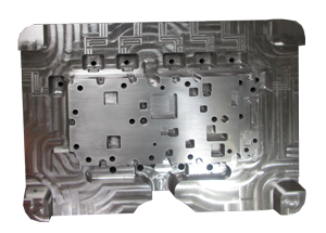
Die casting uses a reusable COMPLEX steel mold, called a die, similar to plastic injection mold. First, the die is split into two main halves and are mounted on an injection machine. Second, the base die is a ridged mount, and the other side is mounted on an opposing hydraulic ram. When the ram closes the two dies, the molten metal is fed into an injector by a ladle and then is injected into the die, called a shot, at high pressures to prevent rather a quick solidification.
Once the metal is solidified, the die is separated, and the finished part is ejected using numerous pins or “pinouts” to eject the finished die-cast with the gates intact. The complete cycle can take 10 seconds to a minute, depending on the size, and then is repeated. As shown in the attached video, a robotic arm can be used to automate this process and even be programmed to reject if there is a problem with the part.
The three mainly used materials that need to be considered are:
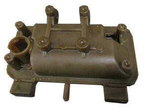
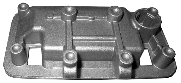
Investment casting, or more commonly known as lost wax, is the oldest and simplest process that produces the highest tightest tolerances of the casting processes.
First, the investment casting process starts with a metal injection mold for wax. This mold is the exact replica of the part required. The mold is then injected with wax and separated, with the wax replica removed.
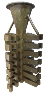
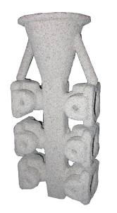
Second, this replica is then attached to a wax gating system with a “sprue” at the top, sometimes called a tree for the way it looks.
Third, this complete assembly is dipped into a ceramic solution in the investment casting process. Then additional ceramic particles are dropped or blown on top of this ceramic base forming a thick layer. Depending on the part design, this process could be repeated.
Fourth, the “tree” is then put in a furnace at 1000°F-2000°F first to melt out all the wax and secondary strengthen the ceramic tree mold.
Fifth, the ceramic tree mold is then removed from the furnace, and the molten metal is poured into the sprue and allowed to cool.
Last, the solidified tree is then sent to an agitator or water jet to remove the ceramic coating depending on the material and design requirements. Then runners are removed from the investment casting.
If any secondary processes are required, they are performed now; however, many investment castings are designed to be used as-is.
First, for selecting the correct casting process, about 70% comes down is what is the industry standard for your part. You should investigate what others are doing for similar products and if there are no codes and stands that regulate the manufacturing of that part. If you find nothing within your industry, you need to evaluate your quantity, size, and finish requirements and try to fit it in the above strengths and weaknesses unless your part is large, then you can only use the sand casting process.
Second, the last two items you must consider are a “Cradle to Grave” and a FULL-SERVICE COMPONENT CONTRACT MANUFACTURER.
FULL-SERVICE means the contract manufacturer can provide you with a finished cast part including machining, PEM/Fastener installation, Powder Coating, & silk screening/engraving, a “one-stop-shop“ eliminating having to resend out your part for a secondary process to separate multiple vendors. This makes controlling processes errors from numerous sources difficult.
“Cradle to Grave” means as your product matures, we will continually give you suggestions (process changes, material changes, sub-assemblies) to reduce your cost giving you an improved sales advantage. An example would be at the beginning of marketing your product, PROTOTYPING, your volumes are low, and you do not want to invest in die-cast mold and manufacturing quantity.
Ionthis could make your finished part or parts from machining from a solid block or fabrication or from sand cast or investment cast or even economically machine the part from a solid metal block. Your NRE investment would be low, but the part price might be higher but absorbable. When your volume gets high enough to justify die cast, then Ionthis can move you into a Die Cast. This is “Cradle to Grave.”
For a DFM/Analysis and recommendations of your Die Cast, Investment Cast, and Sand Cast component or assembly, feel free to contact Ionthis at engr@ionthis.com.